 |
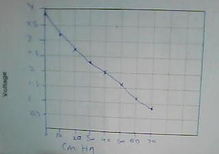
| graph of map sensors output voltage under pressure |
By the results from the graph it shows that this map sensor is good and is working as it should. What shows this is as vacuum is added the voltage goes down accordingly.
MAP sensor On-car
Engine: toyota 1zz
Because the 1zz engine that i worked with had an after market ECU, the MAP sensor was built inside the ECU. So to do some tests i had to use the pins on the circuit board on the engine stand.
With the engine not running but with the ignition on i tested the signal wire with a multimeter on DC volts and got a reading of 4.56V, this reading is showing that the air pressure inside the intake is at atmospheric pressure which is a calibrated value.
Once i started the engine and let it idle i got a reading of 0.43V which indicates a high vacuum is present in the intake. I gave the engine rev to about 2500rpm (about quarter throttle) and got a reading of 2.24V which means there is less vacuum than at idle because of the throttle butterfly letting more air through the intake.
The MAP sensor lets the ECU know how much air comes into the engine by sending various voltage signals to it, these voltage signals depend on how much air pressure is present in the intake manifold.
The readings i got from the MAP sensor for this engine were correct, i Know this because the voltage changes were correct.
 |
| wiring for map sensor |